|
|
|
|
|
|
Part 1: Background: A Nonlinear Oscillator
Our first figure shows an RLC circuit, which contains a voltage source that produces E(t) volts, an R-ohm resistor, an L-henry inductor, and a C-farad capacitor.

For purposes of this module, we assume the voltage source is a battery, i.e., E(t) is a constant E. (The circuit also contains a switch -- not shown -- that determines when the measurement of time starts.) When the switch is closed, a current I(t) (measured in amperes) begins to flow. I(t) is also the rate of change of the charge Q(t) on the capacitor, measured in coulombs. According to Kirchhoff's Voltage Law, current in the circuit is modeled by the equation

If we differentiate both sides of this equation, we find the second-order linear differential equation for the current function:

This is the familiar constant-coefficient, homogeneous equation that represents a damped harmonic oscillator.
If we write V = V(t) = Q(t)/C to represent the voltage drop at the capacitor, we may also represent the circuit by a first-order system of equations:

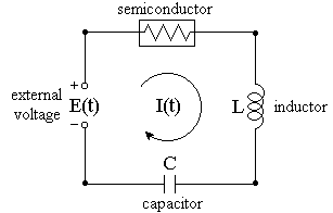
Now we turn our attention to a type of circuit -- from an early radio receiver -- studied in the 1920's by Balthazar van der Pol. This circuit is an RLC loop, but with the passive resistor of Ohm's Law replaced by an active element. In the 1920's this element was an array of vacuum tubes; now it is a semiconductor device. Thus, our circuit becomes

Unlike a passive resistor, which dissipates energy at all current levels, a semiconductor operates as if it were pumping energy into the circuit at low current levels, but absorbing energy at high levels. The interplay between energy injection and energy absorption results in a periodic oscillation in voltages and currents.
We suppose a power supply is attached to the circuit as shown, and the circuit is energized. Then, at time t = 0, the external source is switched out, so E(t) = 0. We will examine how the voltages and current change from then on. The voltage drop at the semiconductor, instead of being a linear function of I(t), is the nonlinear function I(I2-a), where a is a positive parameter. Note that this function is negative for small (positive) values of I and positive for larger values of I. Since current can flow in either direction in the circuit, all three sign changes of this cubic expression are significant.
For convenience, we will suppose that units are chosen in which L and C are both 1. In particular, this means that Q = V, the voltage drop at the capacitor, and I = dV/dt. Our modified Kirchhoff's Law equation then becomes the van der Pol equation*:

* The name van der Pol is used to refer to a family of cubic differential equations and systems with similar properties. The particular equation we study here -- as presented in the source referenced on the title page -- may not be the same equation as "the van der Pol equation" in some differential equations textbooks.
|
|
|
| modules at math.duke.edu | Copyright CCP and the author(s), 1998-2000 |